Yepoleb
Installing ESPHome on Eurom Alutherm convection heaters
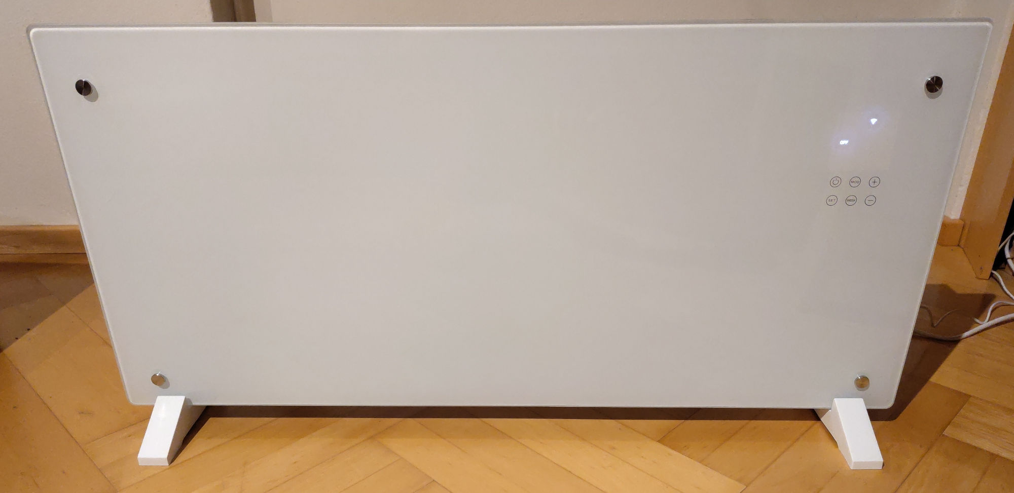
For about a year we’ve been using Eurom Alutherm heaters to heat our home, managed by Home Assistant and later a custom temperature control solution based on MQTT. To get local control of the devices they need to be flashed with a custom firmware, I’ve decided to use ESPHome. I’ve recently had to convert another device and decided to document the process, since it’s been working really well. The disassembly and soldering steps and documentation thereof has been done by my partner Lucia.
Tools and Materials
- PH1 screwdriver
- PH2 screwdriver
- Soldering iron/station with solder
- a 1x6 pin header (Alternatively cut a larger pinheader to size)
- Jumper wires
- UART adapter with 3.3V supply or MCU devboard that can be repurposed
Disassembly
In order to get to the Tuya Board in question we first have to disassemble the convection heater itself. I recommend doing this on a soft surface like a carpet in order to avoid damaging your floors. Of course, as you are working with a mains voltage device, always keep the mains power disconnected while working with the device open. This guide is written for the Eurom Alutherm 2000, but can be applied to similar models such as the Eurom Alutherm 1500.
At first we need to remove the feet of the heater. Therefore we have to lay the heater on it’s back. We now have access to two screws for each foot, which can be removed with an PH2 screwdriver. Afterwards the feet can just be pulled off and the device be put down on its back.
Next, flip the convection heater on its front. You should now be able to see 14 PH2 screws (the exact number of screws depends on your model) with small rims at the edges of the frame - see the image below for reference of their locations on the Eurom Alutherm 2000. In order to open the case these have to be removed, however make sure that you do not remove any screws belonging to the internal power and control assembly, which are slightly smaller in diameter, nor screws on the inner parts of the frame.
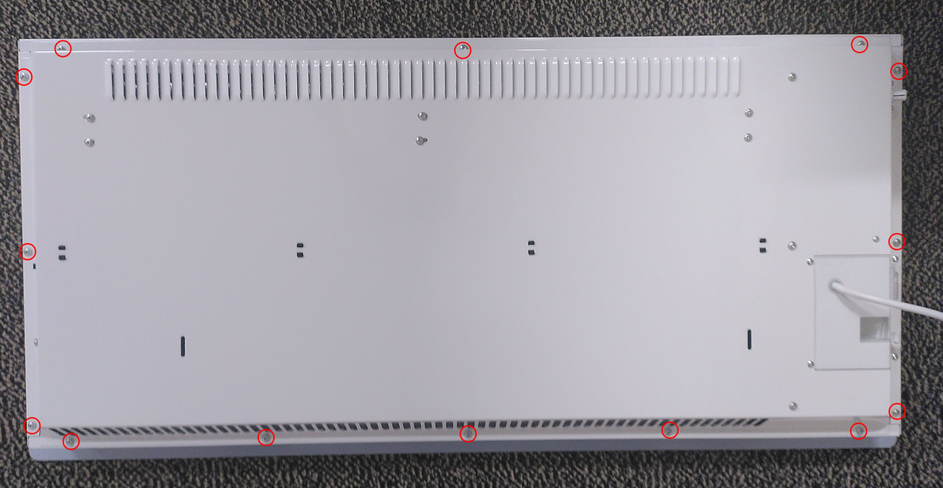
After that the backcover can be be lifted of the front. Turn the backcover around so that you have access to the internals and store the front cover in a safe place. On the right side of the device you’ll find an white plastic box with some cables leading to it, it also houses the capacitive buttons and the LCD screen of the device. This casing is held closed with six PH1 screws. These have to be removed and the plastic casing can now be opened.
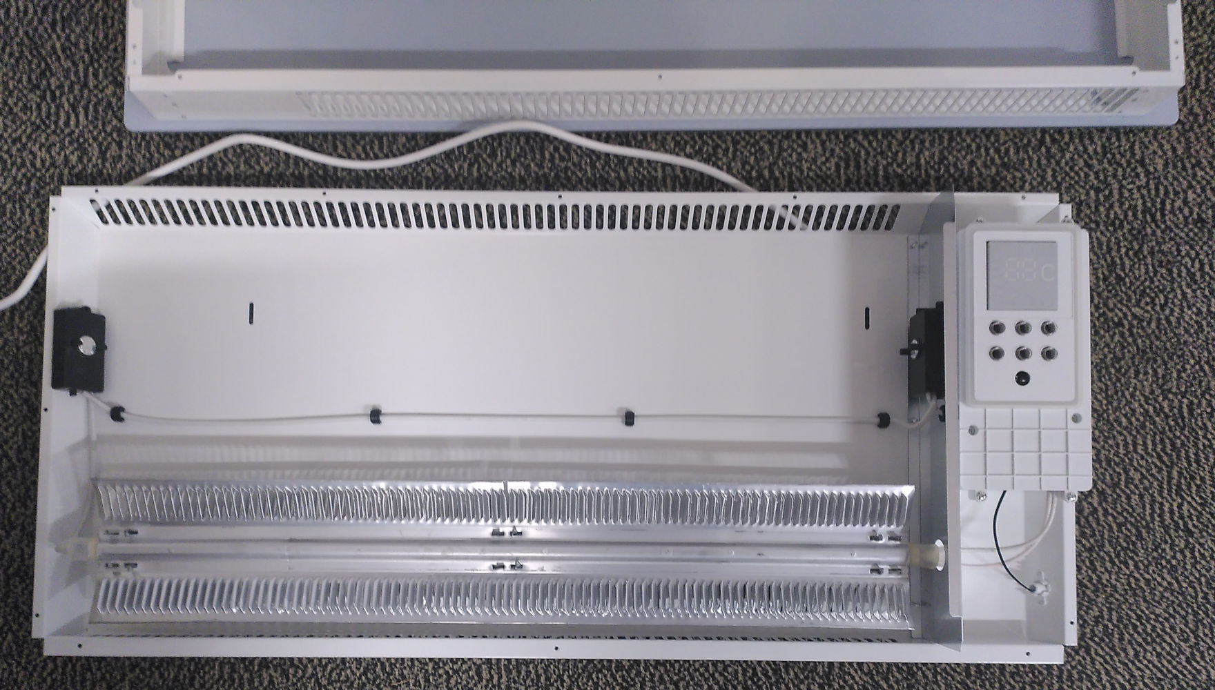
Inside the case there’s one last obstacle we have to remove in order to get to the Tuya board: the main control board, which has four PH1 screws holding it in place. Take note that if the device was already in operation the plastic of the box might have slightly deformed so the screws might not come out straight, therefore take some caution so not to strip the screwheads. The controlboard can be lifted away as shown below, revealing the Tuya board on the top left side.
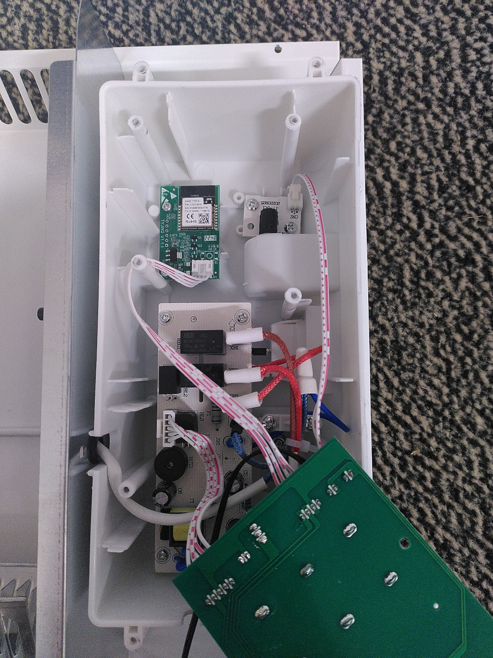
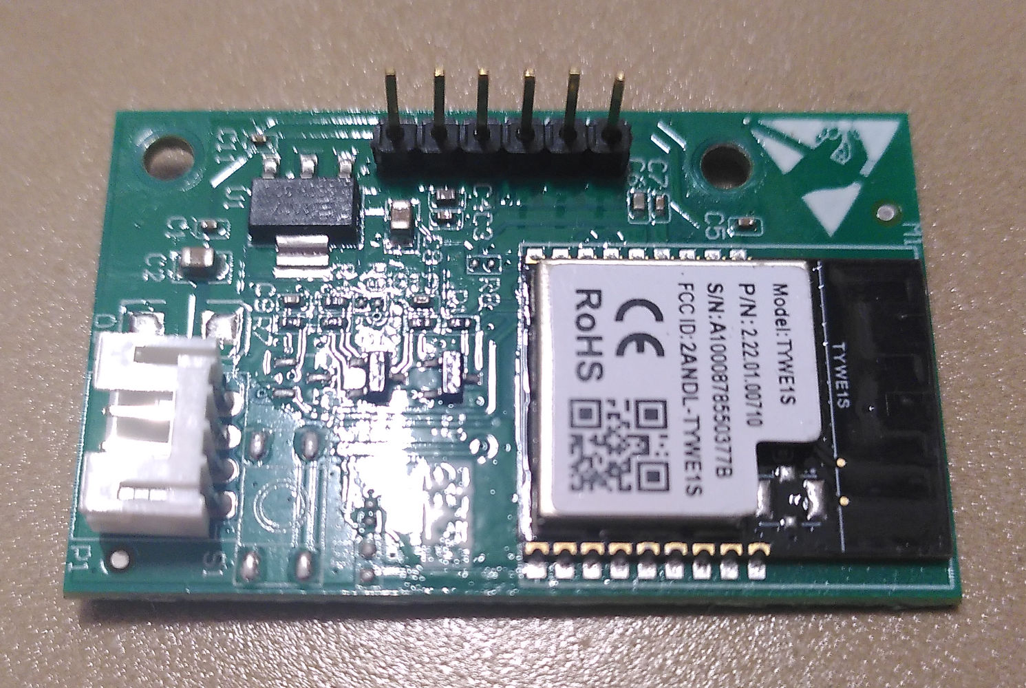
The Tuya board itself is secured with two PH1 screws. After removing those the board can be lifted out and the 4 pin connector attached to it unpluged. The board is labeled TYWE1S on the front and TYJW2.1 on the backside.
Soldering on the pinheaders
After successfully removing the board, next pinheaders should be attached to the debug pinholes in order to be able to flash the device. We now need the 1x6 pinheader. This should be soldered so that the pins protrude from the upper (populated) side of the board. I soldered at 350°C with a small size soldering tip. Take special care when soldering in the ground (GND) pin, the pin has to be preheated for an extended amount of time as it has the biggest thermal mass attached to it. The other pins shouldn’t be to difficult to solder in comparision. If you want to make sure that the GND is properly soldered you can meassure resistance from it to to the GND pin on the 4 pin connector on the bottom of the board. If you get no significant resistance (I got 0.6 Ohm) you probably have done it correctly.
Backing up the firmware
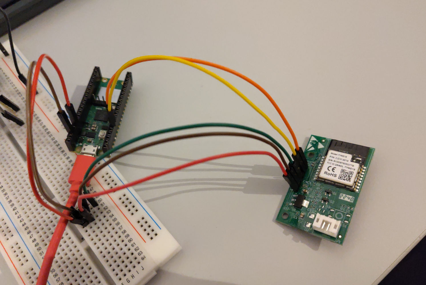
For flashing the board you need a UART adapter with 3.3V logic levels and a power pin. I used a Raspberry Pi Pico with pico-uart-bridge installed. The 3.3V, GND, RX0, TX0 pins of the Tuya Board should be connected to the adapter and the BOOT pin must be tied to ground and can be left that way through the whole process. I used a separate breadboard for that 3-way connection. The TX1 pin can be left floating. After connecting everything you should first take a backup of the existing firmware in case it needs to be restored, because Tuya firmware has a unique device ID. If esptool does not detect a chip try swapping the RX and TX pins. The --before no_reset and --after no_reset options are necessary because the external serial adapter can’t do a chip reset.
esptool --chip esp8266 -p /dev/ttyACM0 -b 115200 --connect-attempts 1 --before no_reset --after no_reset read_flash 0x000000 0x200000 tuya.bin
Building esphome and flashing
I have provided an example configuration file. It needs to be built with esphome compile since initial flashing of the device has to be done manually. Afterwards OTA updating can be used.
If you have your Tuya board still plugged in from the previous step, it needs to be restarted or it won’t accept commands.
esptool --chip esp8266 -p /dev/ttyACM0 -b 115200 --connect-attempts 1 --before no_reset --after no_reset write_flash 0x0 .esphome/build/alutherm/.pioenvs/alutherm/firmware.bin
Reassembly
No special steps needed, simply put everything back together.